Series Z Hydro Pneumatic Systems

Series Z Hydro Pneumatic Systems
The series ‘Z’ Hydro-Pneumatic Systems have been developed for applications where two or more Cylinders have to be operated from a single Reservoir-Intensifier Power unit. They are also useful for applications requiring a large travel under load (large Power Stroke) and for applications where the length of our standard ‘N’ series Hydro-Pneumatic Press systems cannot be accommodated.
The System Consists of :-
(a) An integral Intensifier-Reservoir unit
(b) Single or several Hydraulic Cylinders connected to the Intensifier-Reservoir unit through suitable high pressure flexible hoses and operated by solenoid valves
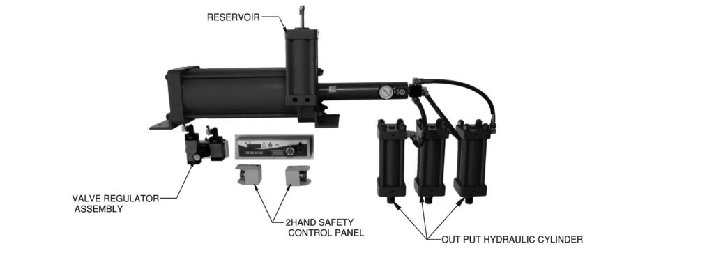
Intensifier
| MODEL | RATIO | OUTPUT OIL PRESSURE @ 5 BAR | MAX. OIL DISPLACEMENT FOR POWER STROKE (cc) | FREE AIR CONSUMPTION PER CYCLE (LITERS) | SEAL KIT No. |
|---|---|---|---|---|---|
| 80-14-200 | 32 | 160 | 27 | 11.8 | 129-001 |
| 80-14-400 | 32 | 160 | 57 | 23.7 | 129-001 |
| 80-20-200 | 16 | 80 | 55 | 11.6 | 129-002 |
| 80-20-400 | 16 | 80 | 110 | 23.4 | 129-002 |
| 100-16-200 | 39 | 195 | 35 | 13.6 | 129-018 |
| 100-16-400 | 39 | 195 | 75 | 37.2 | 129-018 |
| 100-20-200 | 25 | 125 | 55 | 18.4 | 129-003 |
| 100-20-400 | 25 | 125 | 117 | 37.0 | 129-003 |
| 100-28-200 | 12.5 | 64 | 117 | 31.7 | 129-004 |
| 100-28-400 | 12.5 | 64 | 230 | 36.2 | 129-004 |
| 160-32-200 | 39 | 195 | 140 | 47.6 | 129-005 |
| 160-32-400 | 39 | 195 | 300 | 95.3 | 129-005 |
| 160-40-200 | 25 | 125 | 220 | 45.6 | 129-006 |
| 160-40-400 | 25 | 125 | 470 | 93.5 | 129-006 |
| 160-56-200 | 12.5 | 64 | 470 | 72.5 | 129-009 |
| 160-56-400 | 12.5 | 64 | 923 | 144.8 | 129-009 |
| 200-32-200 | 39 | 195 | 300 | 148.8 | 129-007 |
| 200-40-200 | 25 | 125 | 470 | 73.9 | 129-008 |
| 200-40-400 | 25 | 125 | 930 | 147.6 | 129-008 |
| 200-56-200 | 12.5 | 64 | 430 | 72.5 | 129-009 |
| 200-56-400 | 12.5 | 63 | 923 | 144.8 | 129-009 |
*Add Voltage & Connector Suffix While Ordering
Hydraulic Cylinder
| MODEL | FORCE (Kgf) @ 5 BAR | OIL DISPLACEMENT (cu cm) | FREE AIR CONSUMPTION PER CYCLE (LITERS) | SEAL KIT No. | ||
|---|---|---|---|---|---|---|
| APPROACH | RETURN | PER mm TRAVEL | FOR TOTAL TRAVEL | |||
| Z50-50 | 98 | 58 | 2 | 100 | 0.35 | 129-014 |
| Z50-100 | 98 | 58 | 2 | 200 | 0.7 | 129-014 |
| Z50-150 | 98 | 58 | 2 | 300 | 1.0 | 129-014 |
| Z50-200 | 98 | 58 | 2 | 400 | 1.4 | 129-014 |
| Z80-50 | 250 | 171 | 5 | 250 | 1.0 | 129-015 |
| Z80-100 | 250 | 171 | 5 | 500 | 2.0 | 129-015 |
| Z80-150 | 250 | 171 | 5 | 750 | 3.0 | 129-015 |
| Z80-200 | 250 | 171 | 5 | 1000 | 4.0 | 129-015 |
| Z100-50 | 392 | 269 | 8 | 400 | 1.6 | 129-016 |
| Z100-100 | 392 | 269 | 8 | 800 | 3.2 | 129-016 |
| Z100-150 | 392 | 269 | 8 | 1200 | 4.8 | 129-016 |
| Z100-200 | 392 | 269 | 8 | 1600 | 6.4 | 129-016 |
| Z160-50 | 1000 | 850 | 20 | 1000 | 5.0 | 129-017 |
| Z160-100 | 1000 | 850 | 20 | 2000 | 10.0 | 129-017 |
| Z160-150 | 1000 | 850 | 20 | 3000 | 15.0 | 129-017 |
| Z160-200 | 1000 | 850 | 20 | 4000 | 20.0 | 129-017 |
*Add Voltage & Connector Suffix While Ordering
Reservoir
| MODEL | VOLUMETRIC OIL DISPLACEMENT FOR APPROACH (cc) | FREE AIR CONSUMPTION PER CYCLE (litres) | SEAL KIT No. |
|---|---|---|---|
| 80-400 | 400 | 2.3 | 129-010 |
| 80-800 | 800 | 4.5 | 129-010 |
| 100-1200 | 1200 | 7.0 | 129-011 |
| 160-2200 | 2200 | 10.8 | 129-012 |
| 200-4700 | 4700 | 18.0 | 129-013 |
| 200-6000 | 6000 | 36.1 | 129-013 |
*Add Voltage & Connector Suffix While Ordering