
Dual Safety Solenoid Valve For Mechanical Power Press

DUAL SAFETY SOLENOID VALVE FOR MECHANICAL POWER PRESS

Dual Safety Solenoid Valve For Mechanical Power Press
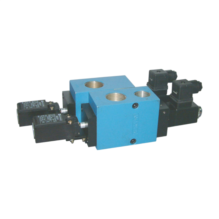
Mercury Pneumatics’ Dual Safety Solenoid Valve for Mechanical Power Press is specifically designed to enhance operator safety and ensure reliable control of clutch and brake systems in mechanical power presses. Engineered to meet the demanding requirements of press applications, the valve incorporates a dual-channel safety design that helps prevent unintended machine operation and provides a higher level of operational safety.

The valve continuously monitors the performance of both channels and is designed to detect faults, ensuring that the press operates only under safe conditions. Its robust construction, fast response time, and dependable performance make it ideal for high-cycle industrial environments where safety, reliability, and compliance are critical.

Suitable for integration into new machines as well as safety retrofit projects, Mercury’s Dual Safety Solenoid Valve helps manufacturers improve workplace safety, reduce downtime, and enhance machine productivity.


Enquire Now

Key Features

  • Designed specifically for mechanical power press applications
  • Dual-channel safety architecture for enhanced operator protection
  • Fast response for reliable clutch and brake control
  • Fault detection and monitoring capability
  • Robust construction for long service life
  • Suitable for high-cycle industrial operations
  • Easy integration into press control systems
  • Helps improve machine safety and operational reliability

Mercury’s Dual Safety Solenoid Valve provides the confidence of safe, dependable, and efficient press operation while supporting modern industrial safety requirements.

DUAL SAFETY SOLENOID VALVE FOR MECHANICAL POWER PRESS

MODEL No. DESCRIPTION SIZE (BSP) SEAL KIT No.
P515 * 3/2 (3 WAY) N.C.
DUAL SAFETY SOLENOID
VALVE
3/4″ SKP515


*Add Voltage & Connector Suffix While Ordering

DUAL SAFETY SOLENOID VALVES WITH SWITCH REACTORS

1. FUNCTION

(a) This solenoid valve is used as a FAIL SAFE device for operating pneumatic
clutches / brakes on Power Presses and similar other machines needing such
special protection.

(b) Every operation of the valve is sensed by two limit-switches actuated by the
valve poppets. In the event of a valve failure, its limit-switch cuts off the main
control circuit of the machine, thereby preventing any further operation of the
machine till the failure is rectified.

2. CONSTRUCTION

(a) The valve consists of two 3/2 (3 Way) Normally Closed solenoid valves connected
in series, with each valve having an independent Exhaust. An extension of the
valve poppets actuates the limit-switches mounted on the valve. Both the
solenoids are connected in PARALLEL and operated simultaneously. When both
coils are DE-ENERGISED, the Cylinder Air escapes through the two Exhaust Ports.

(b) When both the coils are ENERGISED the INLET Air is connected to the
Clutch/Brake Cylinder and both the Exhaust Ports are closed.

(c) In the event of any one of the valves getting ‘Jammed’ or malfunctioning, the
cylinder air escapes through the operational valve. At the same time the
limit-switch operated by the defective valve remains OPEN, thus cutting out the
control circuit of the machine and preventing any further operation.

3. ELECTRICAL CONNECTION

(a) The Normally Open points of the limit-switches are connected in series with the
inlet of the main control circuits. In the DE-ENERGISED condition, the
micro-switches are depressed by the valve poppets and hence will show
continuity. The two solenoids are connected in PARALLEL to the source of signal
for their operation in the machine cycle.

4. TROUBLE SHOOTING

(a) The movement of the valve poppets are visible from the Exhaust Ports. Any
sluggish operation or valve ‘Jamming’ can thus be observed during the actual
operation of the valves.

(b) It is IMPORTANT that the Exhaust Ports of the valve should NOT be restricted.

(c) In case the valve is operating satisfactorily but the control circuit trips, then the
likely fault is a defective limit-switch.

(d) For the smooth operation of the valve we recommend FILTERED and
LUBRICATED air is supplied to the valve at a MINIMUM Pressure of 3.5 bar and
MAXIMUM Pressure of 9 bar.


FRONT PHOTO 8

Special Valves For Mercury Products


View More

FRONT PAGE

Special Valves For OEM Applications


View More

pet moulding valves1

Special valves for PET moulding machines


View More

Screenshot 2024 09 27 172514 1

High Flow Dual pressure valve for PET Machines


View More

RS05

Rotor Coupling


View More

HP silencer

High Pressure Silencers (40 bar)


View More